Latches
Today we are looking at Latches. They are basic storage circuits, that enable us to store information in bit form. The goal is to have a circuit that has two main inputs. Once the enabling switch, that allows us to write/change the bit, and once the input that determines the state of the bit. Only if the enable switch is pressed, we can use the input switch to set the output bit. While the information we have the enable-switch is not active and try to press the input switch, nothing should happen. For this, we will start with a simple Set-Reset Latch and work ourselves to the more elaborate D-Flip-Flop in the further posts.
Set Latch
Last time we looked at different logic gates. Now we want to use the OR gate that we build to build our first version of a latch. This circuit is interesting since we can not describe it simply with a logic gate, as we could for the logic gates. If we first turn the circuit on, we have A = 0. Assuming that the Output is also at 0, we have B = 0 and therefore again the output at 0. So this seems to be a stable state. What happens if we now change the input A = 1 for a short time? The inputs to the OR gate will be (1 OR 0) = 1. This will set the output to 1, which then in turn will set B = 1. We now have (1 OR 1) = 1, the output still being 1. If we now release A we get (0 OR 1)=1 and we still see the output 1. If we again press the input A, we are again in the state (1 OR 1)=1 and nothing changes, the output stays 1. With this, we have a latch, that is only once writable. As soon as we pressed A once, the latch will remain in its activated state, even if we stop pressing A. But we can never reset this latch.
Set-Reset Latch (SR Latch)
| A | B | A NOR B |
|---|---|---|
| 1 | 1 | 0 |
| 1 | 0 | 0 |
| 0 | 1 | 0 |
| 0 | 0 | 1 |
We now want a similar circuit, that latches on to one output, but that can be reset. 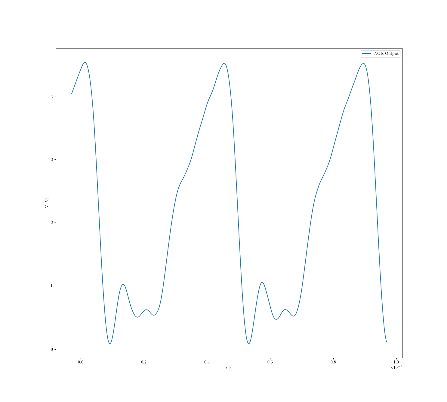 For this circuit, we use an inverted OR gate, or NOR gate. When we build the same circuit as we build with the or gate we see that the output seems to be high and when we press the input button, the output turns low. Let’s first understand the second case. Having a look at the inverted OR table we see, that whenever A is high, the output is low. So this lines up with what we see. In the first case, where A is low, we have two possible states for B. If B is also low, the output is high, the LED is bright. But since we coupled the output to the input of B, this means that now we are in the state (0 NOR 1) which reads 0. Therefore, the output is low, and the LED is off. Again, since the output is the input of B, we turn to the (0 NOR 0)=1 case, and the output turns high. What we actually see here is a very quick flickering of the LED. This we can check using an oscilloscope and measure the output voltage of this ciruit.
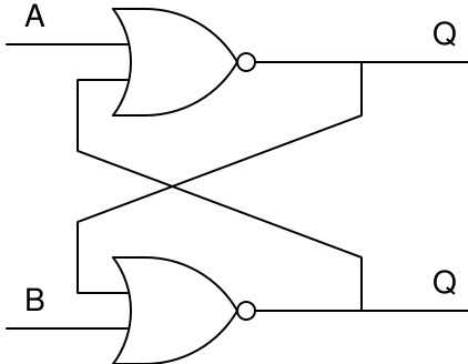
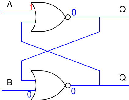
We will later see that this is always the inverse of Q, usually labeled with Q̄. Powering the circuit, we see that the output Q is on. We will color the runs that are “low”, where we have no current, in blue, and the “high” run as red. Let’s try to understand the single outputs.
The inputs A and B are low. We see that Q is high, so the second input for the lower NOR gate is 1. 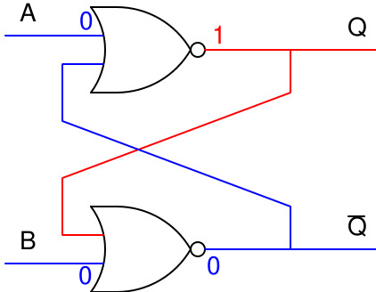 It therefore outputs (1 NOR 0 ) = 0. This output is used as the second input for the upper NOR gate. Its inputs are ( 0 NOR 0 ) = 1. So it seems that this state is actually stable - even though it is not clear why the first output is set topic high. But, assuming that it is, the state is stable.

To check if this is really what we see, we can use our oscilloscope again. Here in blue we see measure the upper output Q, while in orange we plot the lower output. In the beginning, we see that the upper output is high, while the lower output is low.
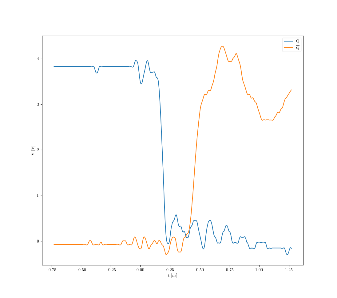 We then press the button, Q goes low while Q̄ stays low as well. Roughly 0.25 ns later, the output Q̄ changes to go high, while Q stays low. We, therefore, see, that the NOR gate needs around 0.25 ns to switch its state. We also see that the gate is not flawless, especially the large fluctuations in the Q̄.
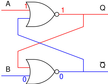
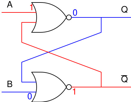
The circuit is now in the opposite position compared to the stable state before. When we now press the input B, nothing happens, while pressing A would result in a similar chain, changing Q and Q̄ again. With these two buttons, we now can flip the output, while pressing the same button multiple times does not change anything anymore. One button is called the Set S, the other the Reset R. Setting the latch using S the output Q goes high. We then can reset the latch using R, changing the output Q to low. When the latch is already set, setting it again does not change its state.
The last mystery we have to address is why the gate started in the configuration that we saw it in. This is because one of our gates was activated quicker than the other one. So this is quite arbitrary.
Summary
We build an SR-Latch that can store one bit of information. It can be reset to be returned in to the original state. This is in contrast to the Set-Latch that can only be set once.