Measuring a Capacitor
Buying stuff from AliExpress
As always, buying stuff from your local dealer at least grants you some sort of quality. But the cheap prices on something like AliExpress are sometimes too good, so I bought a bunch of capacitors there. Before using them, I wanted to make sure, that they work and are correct. Since no oscilloscope was present, I had to build my own small “oscilloscope” out of an Arduino Uno which I had sitting around. This is a small explanation of how to build one and how it works.
The Circuit
The idea behind the circuit is to charge the capacitor and monitor the charging process using the analog readout pins of the Arduino. The voltage over the capacitor is simply given by V(t) = IR(1−e−t/τ). Here R is the resistor over which we charge the capacitor and I is the current. In our case, we use the 5V rail of the Arduino, we simply have IR = U0 = 5V. The time constant τ = RC is the product of the capacitance and the resistor over which we charge the capacitor. This means, when we can measure the time t0 that the capacitor needs to build up a voltage of U0(1−e−1), we can calculate C = t0/R. Since a longer charging time will minimize our relative error in the time measurement, we should choose a large resistor. This also allows us to measure smaller capacitors. I choose a 1 MΩ resistor. The minimal size of capacitors that we can measure with this setup depends on the granularity and readout frequency of the analog pin. Since the readout frequency is relatively small and the granularity is quite limited for the Uno model, we can not measure in the pF region.
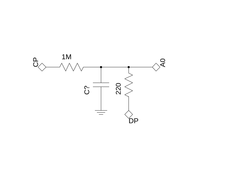 After the Arduino measured the charging time, we want to discharge the capacitor to retake the measurement. This could either be used as a second measurement of the capacitance since the discharge process follows the same law as the charging, but it turns out, that the Arduino has problems measuring lower voltages. This could be a defect on my device or a general problem. Therefore I choose a second resistor, this time with a smaller resistance, to quickly discharge the capacitor and start a new measurement. The A0 pin measures the voltage over the capacitor and therefore determines the time constant. The pin 13 we use as charge pin (CP). When it is set to
 high, the capacitor charges using 5V. As soon as the A0 pin measures a voltage of 0.632 * 5V, the charging process stops, pin 13 is set to low and pin 11, the discharge pin (DP) is activated. This allows the capacitor to quickly discharge over the 220Ω resistor. After this, the pin gets deactivated, preventing the capacitor from accidentally discharging during the charging process.
The code for the Arduino can be found here. It returns the measured charging time in microseconds. I do not calculate the capacitance directly, since my Arduino has only 2bit doubles, so I ran into problems regarding the storage of numbers. The output to the USB Serial Bus can then be loaded into python to determine the capacitance or the times divided by 1.000.000, which results in the capacitance in μF.